Processing is a powerful visualization tool for creating generative art. It’s a native Java library but has been ported to Javascript, Android, and even iOs. Among the many tools, Processing offers artists is the ability to generate lines of all shapes, sizes, and colors.
Generating lines is so easy in Processing that one can almost do it by accident. However, generating squiggly lines can be a bit more of a challenge. In this short tutorial, we’ll use the JavaScript implementation of Processing—P5JS—to explore the process of creating a squiggly line.
Introduction
P5JS is a visualization library designed with 2D generative designers in mind. It is often noted as the tool of choice among generative artists from communities such as the Generative subreddit or popular curated communities such as ArtBlocks (yes, NFTs.)
P5JS is free to use, easy to set up, and very beginner-friendly. The complexity of P5JS is mostly characterized by how an artist chooses to use it. To follow along, you can download the latest P5JS distribution or use the free online editor. Both are available from the official p5JS website here.
Step 1: Drawing a Straight Line
Processing comes with a number of built-in functions to draw basic forms—a line being one of them. The line function takes 4 arguments—2 for the (x, y) coordinates of the starting point and 2 for the (x, y) coordinates of the endpoint.
This function is also overloaded to allow for use of a third coordinate—the z position—of both the starting and ending point if desired. See the documentation for more on that.
To get this party started, let’s set up a basic P5JS scene and select two arbitrary positions from which to draw our line. This is accomplished in the following code:
// Define endpoint variables
let x1;
let x2;
let y1;
let y2;


// Implement the processing setup function
// called once during initialization.
function setup() {

  // Processing
  createCanvas(512, 512);

  // Create start and end points
  x1 = width / 2 - width / 4;
  x2 = width / 2 + width / 4;
  y1 = height / 2 - height / 4;
  y2 = height /2 + height / 4;


}


// Implement the processing function called
// on each frame.
function draw() {

  // Draw background each frame
  background("#efefef");

  // Create a line
  line(x1, y1, x2, y2);
}
Here we’ve implemented the two core functions of processing: setup and draw. The first defines our canvas size and the positions of our starting and ending points are assigned values. The latter is called every frame (60 per second by default, in most cases) and is the main logic of our processing script. This code produces the following image (with notations added for clarification.)

This represents the core approach to drawing a line in processing. The line thickness, color, and fill (depending on what type of line) can all be customized using built-in processing functions. For now, we’re just going to keep cruising with the defaults on our way to downtown squiggletown.
Step 1 – Draw a Multi-Segment Line
A defining trait of the squiggly line is that it has many subsections. That is; where our vanilla line above has a single section between two endpoints, a squiggly line has many sections between endpoints. Before we go any further down this rabbit hole it will prove beneficial to consider the anatomy of a squiggly line:

It’s clear the path towards squiggletown is paved in subpoints. The question now becomes how might we define those points on a line? The trick here is not to define many subpoints along a single line but rather to define many line segments that all interconnect (a.k.a. a polyline.) Let’s consider the following approach:
// Define some global variables
let segments;
let length;
let x;
let y;

// Define the intitialization function
function setup() {
  createCanvas(512, 512);

  // Constrain our lines to 3/4 canvas size
  length = width * 0.75;

  // Define segments
  segments = 6;

  // Define starting points
  x = length / segments;
  y = height * 0.5;
}

// Define the main rendering function
function draw() {

  // Redraw the background each frame
  background("#efefef");


  // Loop through creating lines for each
  // segment.
  for (let i = 0; i < segments; i++){

    // Get the next x point
    let next = x + length / segments;

    // Draw the line from current
    // point to next point
    stroke('black');
    strokeWeight(8);
    line(x, y, next, y);

    // Draw the current point
    push()
    strokeWeight(25)
    stroke("#ff9900")
    point(x, y)
    pop()

    // Update x position
    x = next;

  }

  // Draw the last point
  strokeWeight(25)
  stroke("#ff9900")
  point(x, y)


  // Draw the line once and stop
  noLoop();
}
There are several new additions to our code here. Let’s consider them piece by piece:
- A length and segment variable
- These constrain our line’s width to less than the total canvas area and define how many subsections it will contain.
- A for loop
- The loop generates a new x position to define each segment of our line. It starts at 0 + width * .75 (the left edge of our scaled-down line) and continues until width – (width * .75) pixels (the right edge of our scaled-down line).
- The use of
strokeandstrokeWeightfunctions- These are built-in functions that define how the next elements will be rendered. Here, we’re rendering our line in a “black” color with a weight of 8.
- A point object
- We’re also drawing a point, with a unique color and weight value, to visualize where our line segments are beginning and ending. This is completely optional and included only to help visualize what’s going on.
These steps have produced a straight line with 6 segments. While not yet squiggly—our line is certainly reflecting the skeletal form of something that could squiggle. The following image is produced when running our script (with notes added):

We aren’t squiggling yet—but we’re surely getting closer! The next step is to add a bit of motion to our line such that the points of its inner segments are moved from the boring positions located in the center of the canvas.
Step 3: Add Some Movement
A squiggly line can be understood as having three or more points such that a perfectly straight line cannot be drawn in a way that intersects all three. This is kind of like the opposite goal of linear regression analysis.
With this level of variance, a squiggle can start to reveal itself when each line is connected. To get this effect, we’ll apply a random offset on the Y-axis of each of our points. We can achieve this by replacing our existing line creation code with the following:
function draw() {

  // Redraw the background each frame
  background("#efefef");


  // Loop through creating line segments
  for (let i = 0; i < segments; i++){

    // Get the next x point
    let next = x + length / segments;

    // Get random y
    yRand = random(-(height * 0.25), height * 0.25); // <------------ New

    // Draw Lines
    stroke('black');
    strokeWeight(8);
    // To current point
    line(x, y, next, y + yRand);

    // To next point
    line(x + length/ segments, y, next, y + yRand) // <------------ New


    // Draw points
    push()
    strokeWeight(25)
    stroke("#ff9900")

    // Draw the current point
    point(x, y)

    // Draw the next point
    point(x + length / segments, y + yRand) // <------------ New
    pop()

    // Update x position
    x = next;

  }

  // Draw the last point
  strokeWeight(25)
  stroke("#ff9900")
  point(x, y)

  // Draw the line once and stop
  noLoop();
}
Here we’ve added three new changes that will generate what will reveal itself as the beginnings of a squiggle. These are, in order:
- A randomized value yRand by which to move our points from their previous positions
- An additional line segment;
- An additional point;
With these additions, we can see our code begin to give life to a more organic form reflected in the image below:

This is nice, but there’s an issue that needs ironing out. In our attempt to add motion we’ve inadvertently created a sort of mean-reversion tendency. Notice how, after each progression to a higher or lower Y-value, our line returns to the middle of the image (vertically speaking.) Let’s make the following adjustments in our main for loop body:
// Loop through creating line segments
for (let i = 0; i < segments; i++){

// Get the next x point
let next = x + length / segments;

// Get random y
yRand = random(-(height * 0.125), height * 0.125); // <---------- Lower the yRand range a little

// Draw Lines
stroke('black');
strokeWeight(8);
// // To current point
line(x, y, next, y += yRand); // <----------- hard increment here
// To next point
line(x + length/ segments, y, next, y)


// Draw points
push()
strokeWeight(25)
stroke("#ff9900")

// Draw the current point
point(x, y - yRand) // <----------- avoid mean reversion

// Draw the next point
point(x + length / segments, y)
pop()

// Update x position
x = next;

}
With these three small changes, the following image is produced:

Step 4: Make it Squigglier
Our squiggle is coming along—now reflecting some twists and turns that one might expect. However, it still feels a bit rigid. Squiggles are, after all, free spirits that aren’t bound by the need to get from point A to point B in the fastest route. Squiggles like to squiggle.
To this point, we’ve been drawing things using the line and point functions—with the point function really only for visualization. By leveraging the beginShape and cuveVertex functions we can make things much more smooth. For this, we’ll need to alter our code considerably. Here’s an updated version of our draw() function:
function draw() {

  // Redraw the background each frame
  background("#efefef");

  // Loop through creating line segments
  beginShape()
  noFill()

  // Add the first point
  stroke('black')
  strokeWeight(5)
  curveVertex(x, y)

  // Save points for visualization later
  let points = [{x: x, y: y}] //<----- Add initial point here

  // Draw line
  for (let i = 0; i < segments; i++){

    // Get random y
    yRand = random(-(height * 0.125), height * 0.125);

    // Add point to curve
    curveVertex(x += length / segments, y += yRand);

    // Save point
    points.push({x: x, y: y})

  }
  endShape()

  // Draw points for visualization
  stroke('#ff9900')
  strokeWeight(10)
  points.push({x: x, y: y})
  points.forEach(function(p){
    point(p.x, p.y)
  })

  // Draw the line once and stop
  noLoop();
}
We have consolidated some lines for brevity and changed the way we’re approaching the creation of the yellow points (used only for visualization) to be drawn outside the for loop. This approach calls the beginShape() function, then calls the curveVertex() function for each point on the line, the finishes by calling the endShape() function. Each line segment drawn in this approach gets the styling defined prior to the beginShape(). Here’s the image that is produced:

Now, this is venturing into the land of squiggle! Here we see our line segments being smoothed between points that result in a curve rather than a line. However, we now face a different issue: we’re missing the first and last segments!
Step 5: Make it Whole Again
Processing (and P5JS as well) use a Catmull-Ram algorithm to calculate curves. By this approach, the first and last points in a series are used to “guide” the beginning and end of curves rather than actively partake in their rendering. Let’s consider the official documentation for the curveVertex() function:
The first and last points in a series of curveVertex() lines will be used to guide the beginning and end of a the curve. A minimum of four points is required to draw a tiny curve between the second and third points. Adding a fifth point with curveVertex() will draw the curve between the second, third, and fourth points.
This describes a scenario in which all curves could effectively be missing their first and last segments—just as ours above is suffering. However, let’s consider what might happen when adding duplicates of both our start and end points. Consider the following code:
function draw():

    ...

    // Add the first point
    ...
    curveVertex(x, y);
    curveVertex(x, y); // <---------- add an additional start point here

    ...

    for (let i = 0; i < segments; i++){
    ...
    };
    curveVertex(x, y); // <---------- add an additional end point here
    endShape();

    ...
This essentially uses the first point to “guide the beginning” of the curve to the first point and then a duplicate end point to “guide” the end of the curve as well. It seems a bit nonsensical honestly but it gets us where we want to be—front and center for the squiggliest show in town! Here’s our image now:

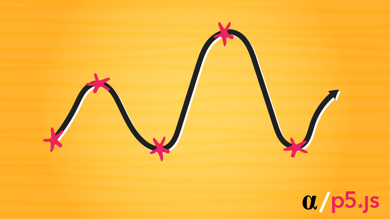
Now that is a squiggly line! It has taken quite a few steps to get here but at long last we have discovered the path to create a multi-segment line (curve) using Processing.
Note: A complete version of the finalized script developed in this post is available via Github.
Important Considerations
Now that we are masters of the squiggly line it might be tempting to run off into the wild and start squiggling all over everything. This would be a mistake—there are some common mishaps that we may fall prey to.
Here is a list of some of the most common gotchas when it comes to using the beginShape() and curveVertex() functions in processing and/or P5JS:
- The
curveVertex()function can only be used where no argument for shape type is given to thebeginShape()function. This includes LINES, TRIANGLES, QUADS, and others. - The
vertex()function can be used in conjunction with thecurveVertex()so long as a single call tocurveVertex()is present within abeginShape()–>endShape()segment. The only upside here is syntactic brevity—a poor trade-off in this case for the confusion it could create. - Using the
CLOSEkeyword as an argument for theendShape()function will draw a line between the first and last points. Oddly enough, this doesn’t cause any issue whether there are duplicate start and endpoints or not—the resulting line is the same.
Final Thoughts
Processing is among the most popular high-level design libraries out there. Whether you choose the original Java library, the P5JS JavaScript implementation, or go mobile-native with the android or iOs versions—processing brings a lot to the table. When getting started with processing it can be frustrating learning how this library approaches certain tasks. Drawing a simple squiggly line, for example, can result in a process much more complicated than one might expect.
Taking the time to learn how processing’s functions are designs, intended to be used, and the benefits they provide is paramount to success with this library. Some of the most popular, renowned, and inspiring images of generative art on the planet have been produced with this software. For those seeking further inspiration, examples, or learning paths I suggest starting at the official Processing.org website where there are ample examples, tutorials, and recommendations for books.